


FLOAT – BOOST CHARGERS DC POWER SUPPLIES
Applications
•Power Stations
•Sub-stations
•Switchgear Stations
•Metal industries,
•Housing Colonies
•Chemical plants
•Electromagnets
•Etc…
Battery Types
•Lead Acid
•VRLA•SMF •Plante
•Nickle Cadmium NiCd
•Tubular Plate •Etc..
Range
•24/30/110/220 VDC
•5 Amps -1500 Amps
•Input 230(1P)/415(3P)
[wpdm_package id=’4752′]
Description
Function
Depending on the application, Lead Acid, VRLA, Ni-cad or Tubular batteries are selected for Stand by application for any Power Plant.
Each type of battery requires an individual charging characteristics which can be achieved by thyristor based/ SMPS based or PWM controlled circuits. These chargers are having Constant Current (CC) and Constant Voltage (CV) control circuits.
They basically consists of transformer, semi-conductor bridge rectifier, filter circuit and control cards.
In Tharistor based chargers ac mains voltage is transformed to suitable level and fed to the rectifier thyristor bridge. Power output requirement is achieved using phase angle control technique. It is feed to load after being smoothed by the filter circuit.
In SMPS based and PWM Controlled battery chargers, AC input supply is rectified and DC source is created.
This is feed to high frequency switching circuitry. In these mode, we can achieve wide input voltage range and output can be set at very precise level. These systems are also highly efficient.
FCBC are also required to supply continuous power to the DC load and simultaneously charge the batteries connected.
In Auto mode the DC power is supplied to he load by the Float Charger. It also supplies trickle charging current to the battery to keep it healthy. If the charging current under Float Mode exceeds a set level, Boost charger is switched ON. It supplies Quick charging current to the battery. On battery reaching the set value, the Boost Charger is switched OFF.
Technical Specification |
|
|---|---|
| Aux: | : 415V. AC ( 3 Phase) / 240 V (1 Phase)+/- 20 %/ +/- 10%, 50 Hz. +/- 3 Hz. |
| Out put | : 30 V, 48 V, 110 V and 220 V. DC supply |
| Battery Type | : Lead Acid / SMF/PLANTE/ NiCd |
| Indications and instruments | : Indications for 3 phase mains supply |
| : Float / Boost section | |
| : AC Volt meter with selector switch | |
| : DC Volt meter with selector switch and battery volt | |
| : DC Amps meter for load | |
| : DC Amps meter for Charging. | |
| Protection | : MCB for Mains incoming supply |
| : MCB for out put load | |
| : Over load cut out by electronics circuit | |
| : Over Voltage cut-out by electronics circuit | |
| : Single phasing, under voltage for mains | |
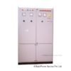
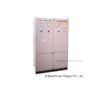
| Housing and Enclosure | : Heavy duty Sheet Steel Enclosure Finished with Powder Coated paint. |
| Operation | : Auto/Manual |
| Control | : CC/ CV close loop |
| Rectifier | : Full wave half controlled bridge |
| Optional | : Fuse protection for each rectifier element |
| : Fuse failure relay | |
| : DC Earth Fault Relay | |
| : Alarm Annunciation | |
| : Dual Float Charger option | |
| : Any other as per requirement. | |
Block Diagram |
 |
Configurations
•Float cum Boost (FCBC)
•Float and Boost(FC&BC)
•Dual Float cum Boost(DFCBC)
•Customized Configuration